We use two receivers: a Kenwood TS-890S and an ICOM IC-7300. Each has its own internal processing delay, so the first task is to determine that delay.
Test setup
We need a pulse signal generator that can lock to an external reference (1 PPS from a GPSDO). Perform the measurements in CW mode.
Feed a pulse signal at 14 MHz with a duration of 10–300 ms into the transceiver.
For the oscilloscope:
- Channel 1: trigger and horizontal sync from the generator’s reference output.
- Channel 2: connected to the transceiver audio output.
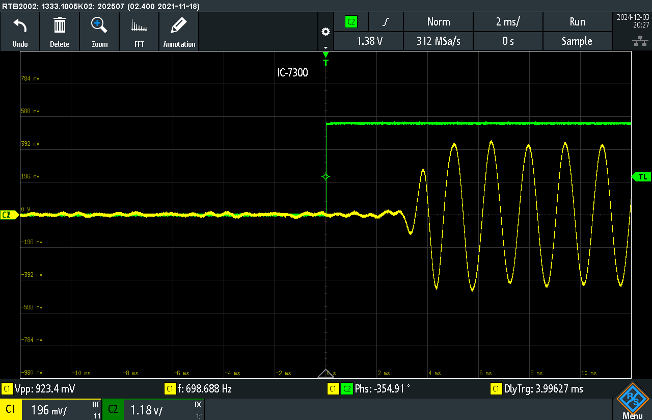
Fig. 1. IC-7300 delay measurement. With no audio filters, the delay is 4 ms.
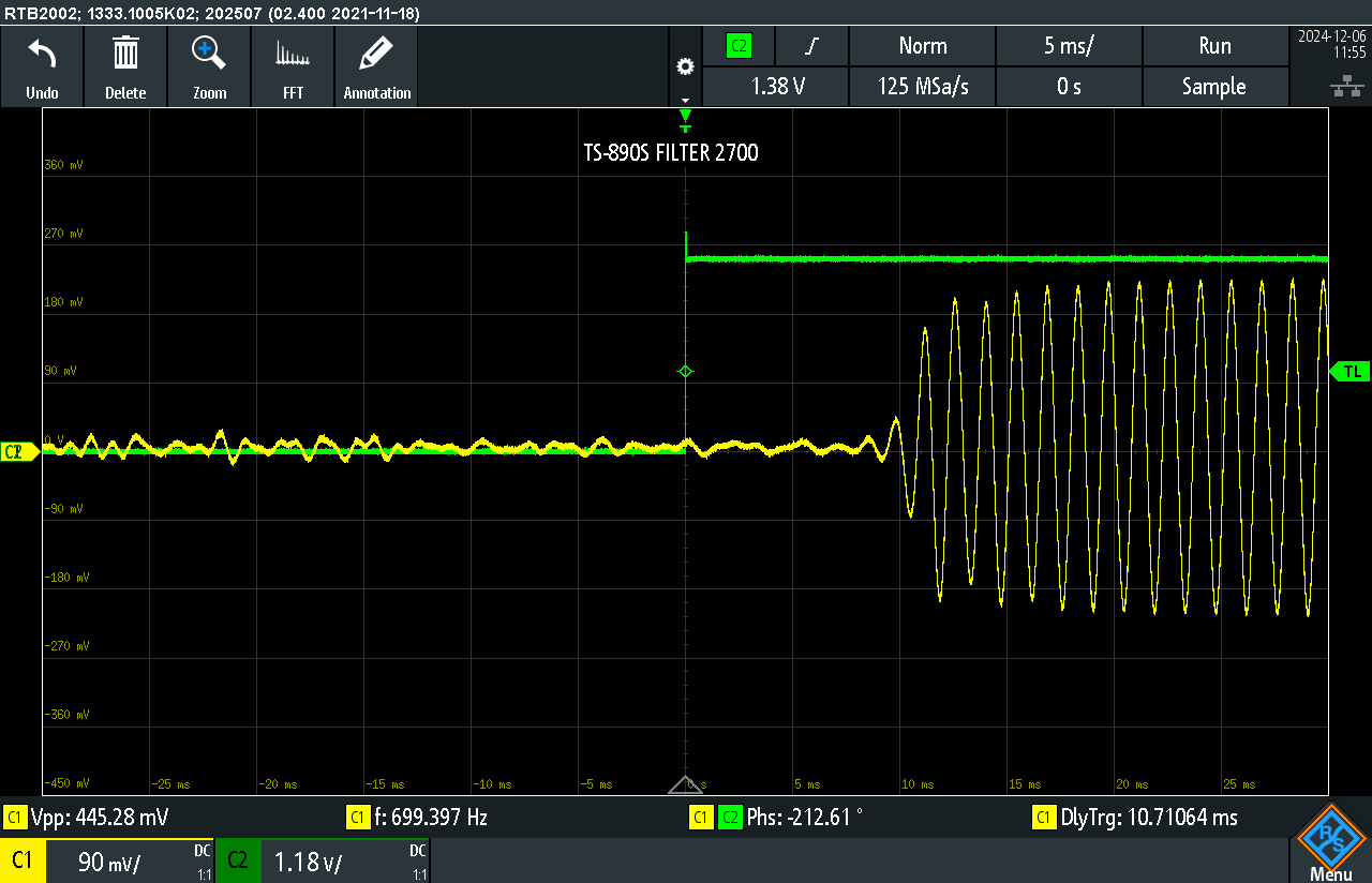
Fig. 2. TS-890S delay with the default 2.7 kHz filter.
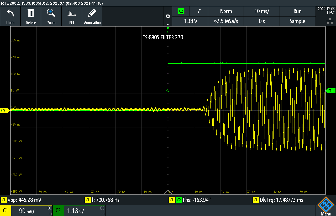
Fig. 3. TS-890S delay with the 270 Hz roofing filter.
As the traces show, you need to measure each receiver individually. It’s also a good idea to run a quick check before on-air work to confirm the settings are correct.
On-air check with RWM
Next, we estimate the distance to the RWM time-signal station near Moscow. According to the transmitter schedule, we tuned to 9.996 MHz and measured the delay of the received signal on the air.
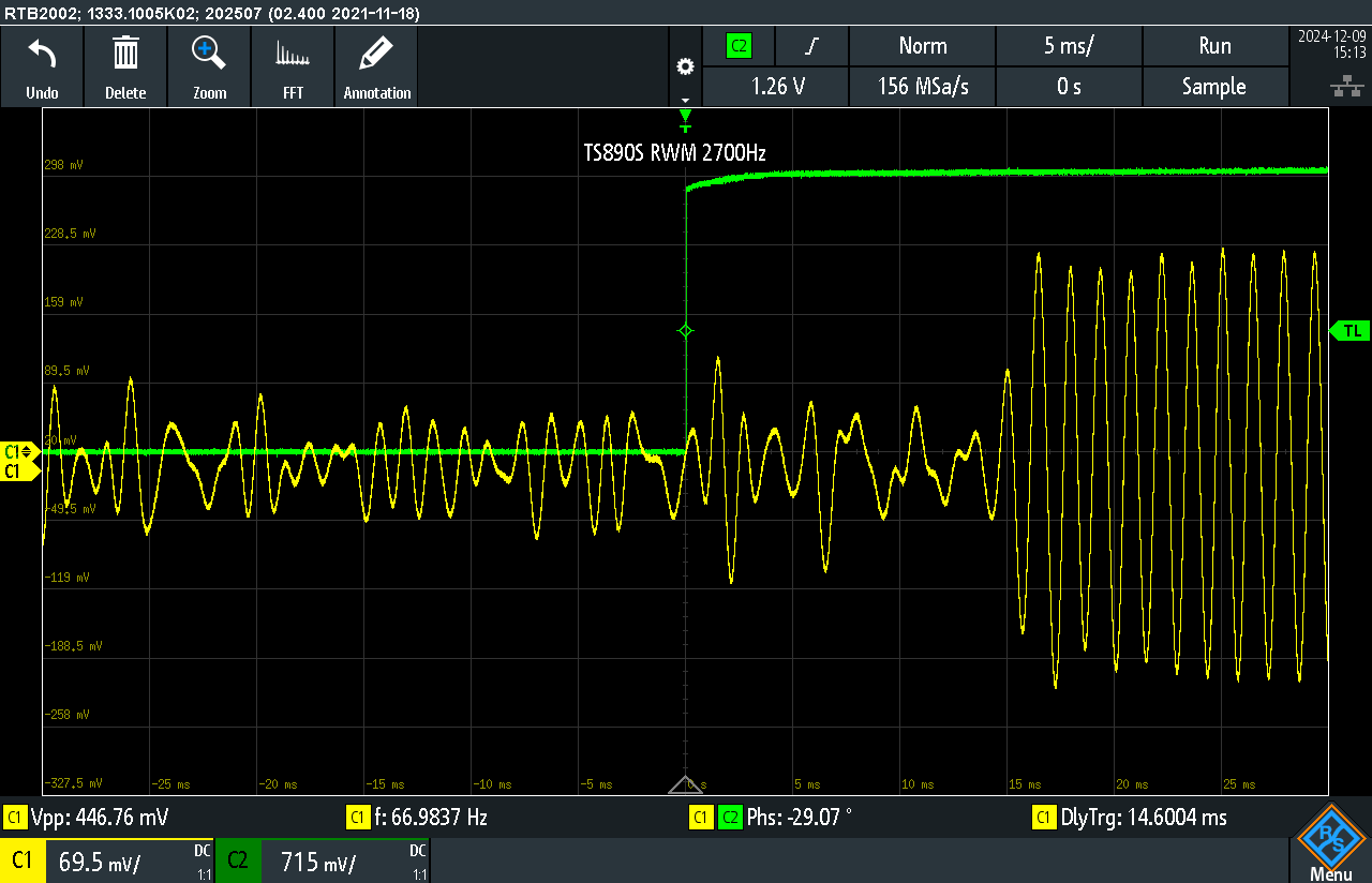
Fig. 4. RWM signal measurement on the TS-890S with a 2.7 kHz filter.
Now calculate the path length, taking the known internal receiver delay into account.
Using the speed of light approximation (1 ms ≈ 300 km):
(14.6 ms−10.7 ms)×300=1170 km
We cross-checked this with Google Maps.
The difference was only 12 km, which is a solid result for an over-the-air measurement.
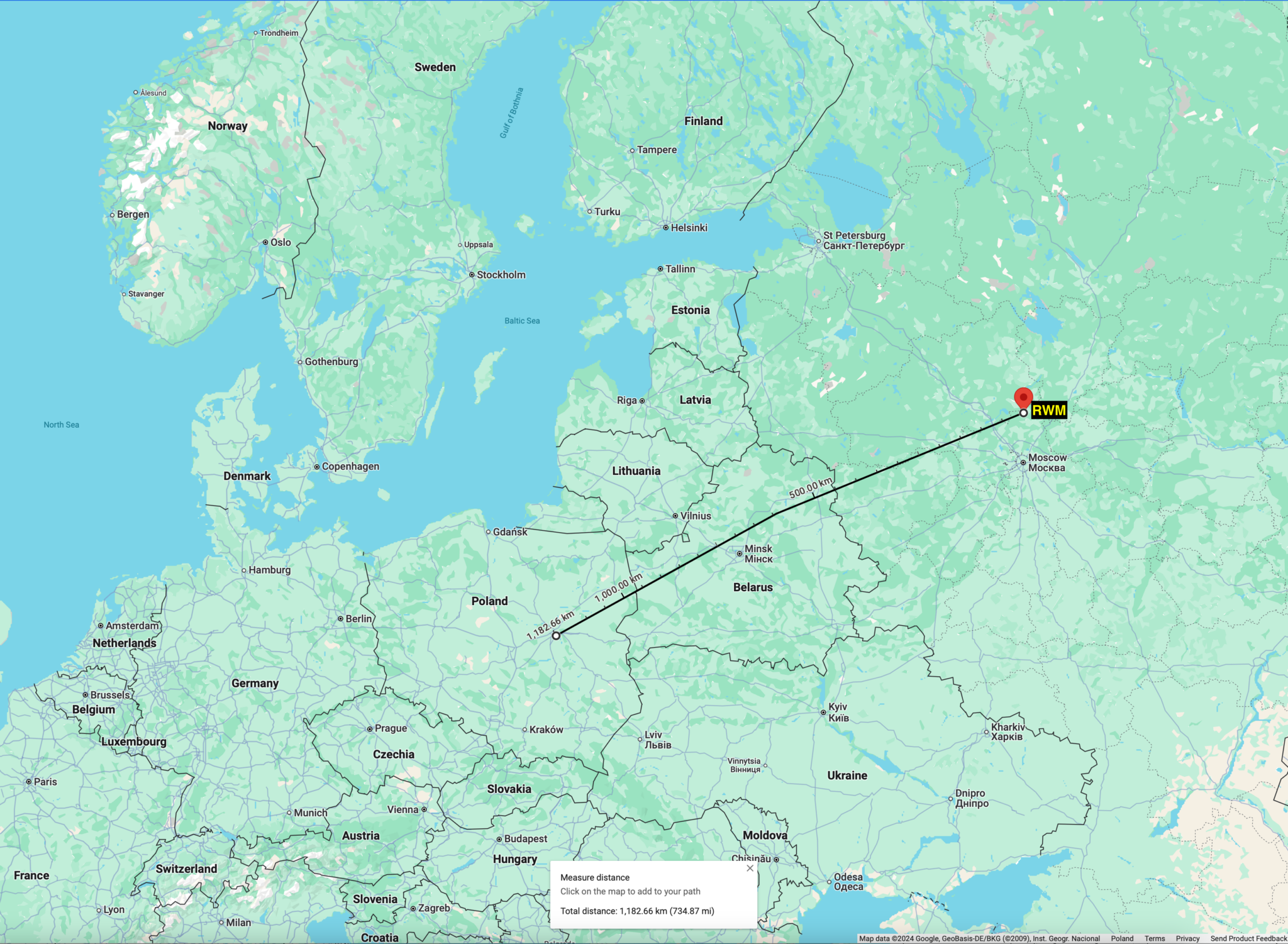
Fig. 5. Distance by coordinates checked on Google Maps.
SP5LST, Konstantin Lisitsyn, December 2024