The development of new technologies inevitably leads to the emergence of new areas of interest. Amateur radio covers a very wide spectrum of activities, but in this article I would like to focus on FMT — Frequency Measuring Tests.
This is a relatively new and still little-known direction among radio amateurs. I will share some of my personal experience of participating in these unique competitions.
On April 21, 2023, I took part in my first FMT event organized by the ARRL. My callsign is SP5LST.
Participation Requirements and Measurement Accuracy
Participation requires appropriate equipment, measuring instruments, and experience in quickly tuning to the transmitted signal frequency, followed by collecting sufficient statistics to determine the frequency accurately.
I was not only able to participate, but also to demonstrate in practice that precise measurements are possible over intercontinental distances. My frequency measurement accuracy was 0.3 Hz on the 80-meter band and 0.4 Hz on the 40-meter band.
The conditions and results can be found at:
https://fmt.arrl.org
FMT Beacon and Pulse-Based Measurements
In the spring of 2023, the RU0LL station was launched as an FMT beacon transmitting short pulses with a duration of 50 ms.
The primary purpose of this beacon is to transmit special signals that can be used for distance determination.
The beacon has been operational in the past and is currently active on an irregular basis. When active, it is available to radio amateurs for calibration of their equipment using known reference values.
Any radio amateur with suitable measuring equipment and a time standard can participate in competitions organized as follows. After calibration and verification of the receiving equipment, on the competition day the same pulse signal is transmitted as in normal operation, but with a deliberate time offset relative to the 1 PPS signal.
This is the main task of the amateur radio engineer: to determine this offset as accurately as possible.
The greater the number of participants from different regions of the world, the more data becomes available, allowing statistical analysis of propagation effects and environmental influences. And of course, everyone is interested in their position in the final results table.
Measurement Methodology
My modest home laboratory allows me to receive the signal and measure pulse durations. Each pulse is synchronized with the 1 PPS signal, which represents the start of each second and, when generated by a highly accurate source, allows precise calibration of measurement equipment.
As a reference source for the 10 MHz and 1 PPS signals, I use a BG7TBL GPSDO. The 10 MHz reference signal is used to synchronize all measuring instruments in my laboratory.
To measure the distance to the transmitting beacon, a local 1 PPS signal is required. The main instrument needed is a dual-channel oscilloscope.
One channel is connected to the local 1 PPS signal, and the other to the audio-frequency output of the receiver. The oscilloscope trigger is synchronized to the 1 PPS signal. The time shift observed between the two signals represents the propagation delay of the radio signal.
Using the well-known approximation of 1 ms corresponding to 300 km, the distance to the transmitter can be calculated.
If the receiving equipment allows, the precise 50 ms pulse duration of the FMT beacon can also be measured for verification and calibration purposes.
Receiver Delay and DSP Effects
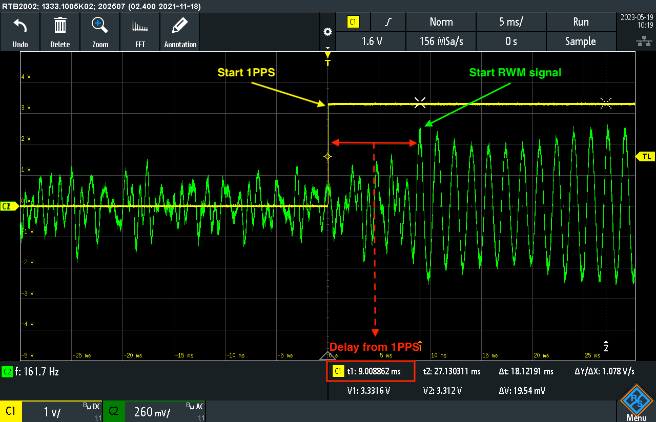
A critical aspect of these measurements is determining the internal delay introduced by the receiving equipment. During my initial measurements using the RWM time signal station in Russia, I observed an error of approximately 5 ms, which would correspond to an additional 1500 km. This is physically impossible.
I assumed that my IC-7300 transceiver introduces internal delay due to analog-to-digital conversion. Alexander RU0LL measured receivers of different generations in his laboratory, and this assumption was confirmed. Any receiver employing DSP introduces a significant delay in the final audio output.
Therefore, to accurately determine the distance between the beacon and the receiving station, this internal delay must be measured and taken into account.
Measurement Example
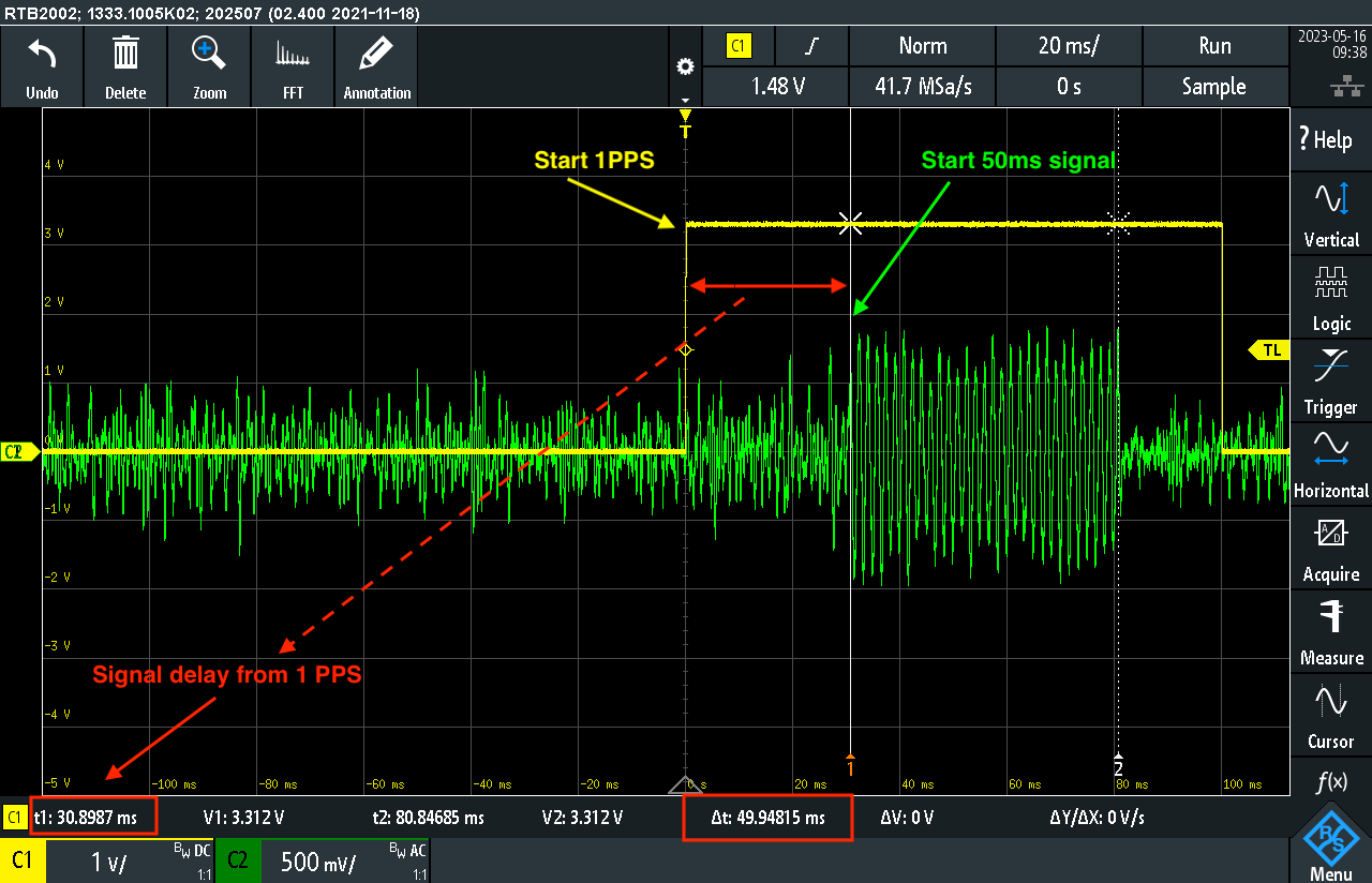
This picture shows an oscilloscope trace of two signals: the local 1 PPS signal and a single received pulse with a duration of 50 ms. A time shift of 30.8 ms relative to the 1 PPS reference is observed.
The internal delay of my transceiver is approximately 5 ms. This value was determined using the known geographic distance between the transmitter and receiver, and was also confirmed by receiving a similar signal from the RWM station on 14 MHz.
Thus, the true propagation delay is:
30.8 ms − 5 ms = 25.8 ms
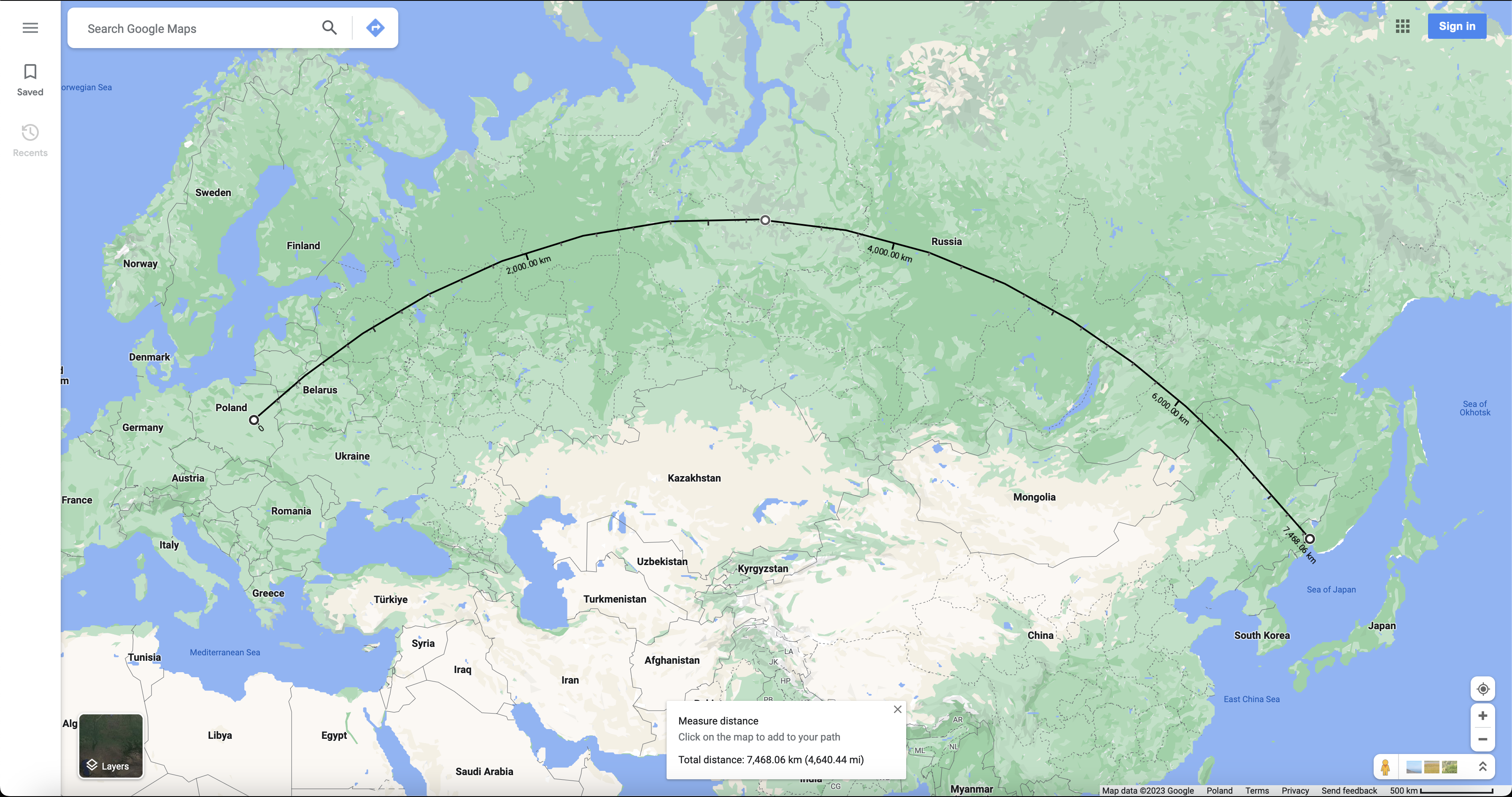
The calculated distance is:
25.8 ms × 300 km/ms = 7740 km
An additional 1 ms delay is present, likely caused by multiple reflections from the ionosphere and the Earth’s surface. For such long distances, a 1 ms deviation is relatively small.
It would be very interesting to obtain similar measurements from colleagues on other continents under different propagation conditions.
Conclusion
FMT combines precision measurement, signal propagation analysis, and experimental engineering. For me, the value of this discipline lies in curiosity, exploration of the unknown, and the desire to create and understand.
I hope that more enthusiasts will join this process so that together we can further develop this fascinating radio direction.
Special thanks to the FMT ARRL project and all participants for the opportunity to engage with advanced measurement techniques and accumulated knowledge.
Thanks to RU0LL for further development of pulse-based measurements of time and distance.
See you on instrument screens and, of course, on the air.
73
Konstantin Lisitsyn SP5LST