FMT Reference Pulse Signal Specification
This document explains the reference pulse signal used in FMTLab. It covers signal timing, structure, 1PPS synchronization, and the recommended measurement method. The goal is to provide a stable and repeatable reference that allows participants to compare real measurement accuracy.
Technical Description of the FMTLab Pulse Signal
1. Purpose of the Signal
The FMTLab transmitted signal is designed for measurement and experimental use, including:
- measuring time delays in transmit and receive paths
- analyzing the impact of filtering, AGC, and group delay
- experiments with time and frequency stability, including 1PPS reference
- FMTLab measurement contests, where participants compare the accuracy, stability, and repeatability of their measurements
The signal is not optimized for radio communication and is not intended for subjective reception quality evaluation.
Its key property is time repeatability and convenience for metrology.
2. Signal Structure
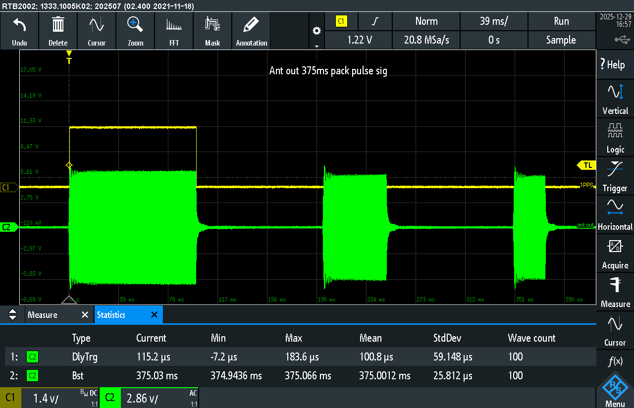
The transmitted signal is a 1 kHz sine wave, formed as three time-limited bursts.
At a typical oscilloscope time scale, the 1 kHz carrier looks like a solid block.
When zoomed in, the sinusoidal structure is clearly visible.
Reference Pack timing:
- Pulse #1: 100 ms
- Pause: 100 ms
- Pulse #2: 50 ms
- Pause: 100 ms
- Pulse #3: 25 ms
Total packet duration:
100 + 100 + 50 + 100 + 25 = 375 ms
(This is the Reference Pack)
Operating modes:
- Calibration sessions:
The full 3-pulse packet (100 / 50 / 25 ms) is used as a test sequence to analyze the signal path and verify the measurement method. - Contest mode:
The target metric is the duration of the third pulse (25 ms).
The first two pulses are used for calibration and validation of linearity, stability, and measurement consistency.
Main signal parameters:
- waveform: sinusoidal
- sine frequency: 1 kHz
- structure: 3 burst pulses in one packet
3. Measured Parameters at the Antenna Output
All timing measurements were performed using a Rohde & Schwarz RTB2002 digital oscilloscope.
Measurements were taken directly at the antenna output.
The values below show statistics over multiple captures.
The spread is defined by timer resolution and analog path delays.
No long-term drift was observed within a measurement series.
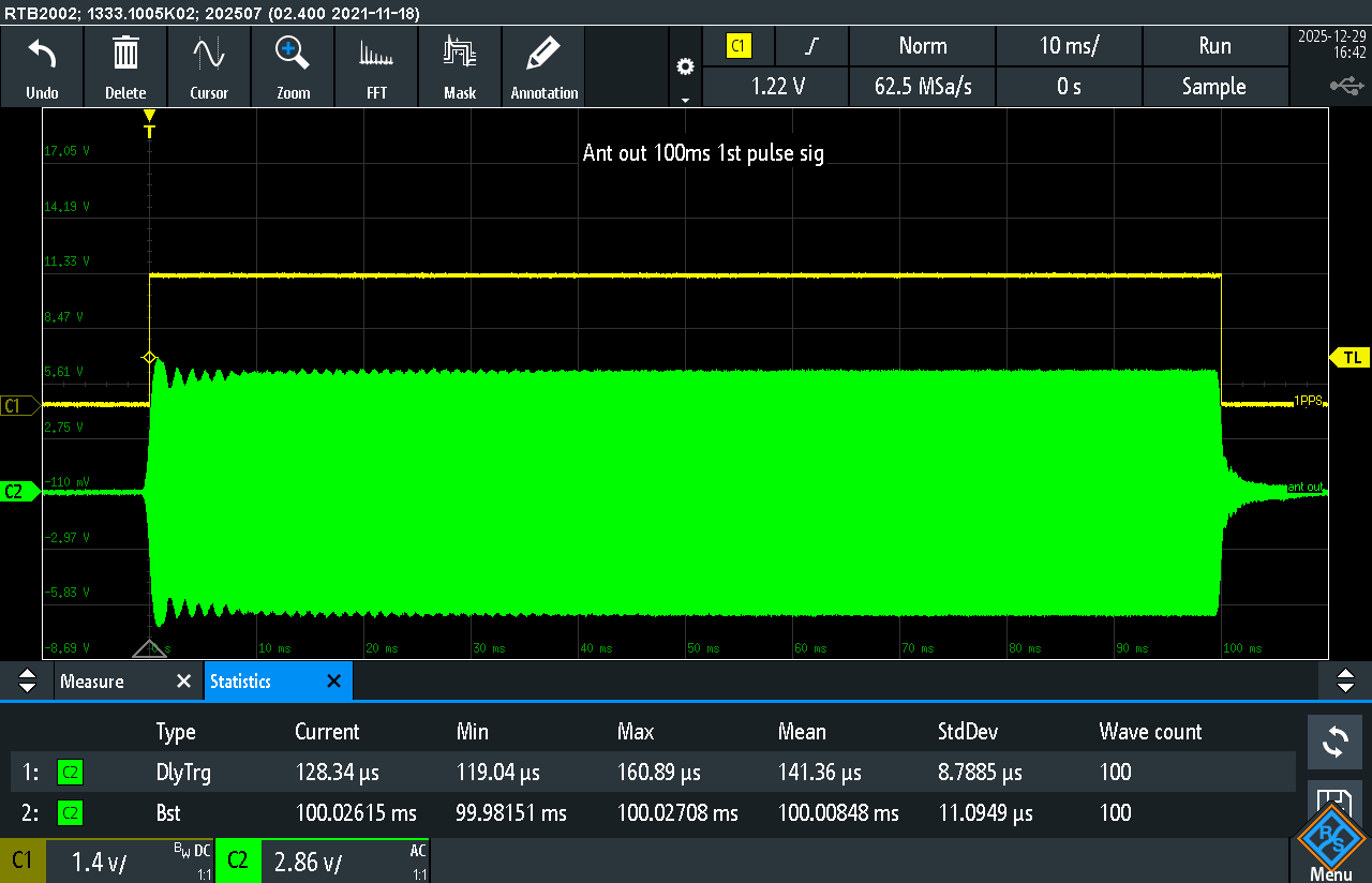
Pulse #1 (nominal 100 ms):
- Mean: 100.00848 ms
- Min–Max: 99.98151 … 100.02708 ms
- StdDev: 11.09 µs
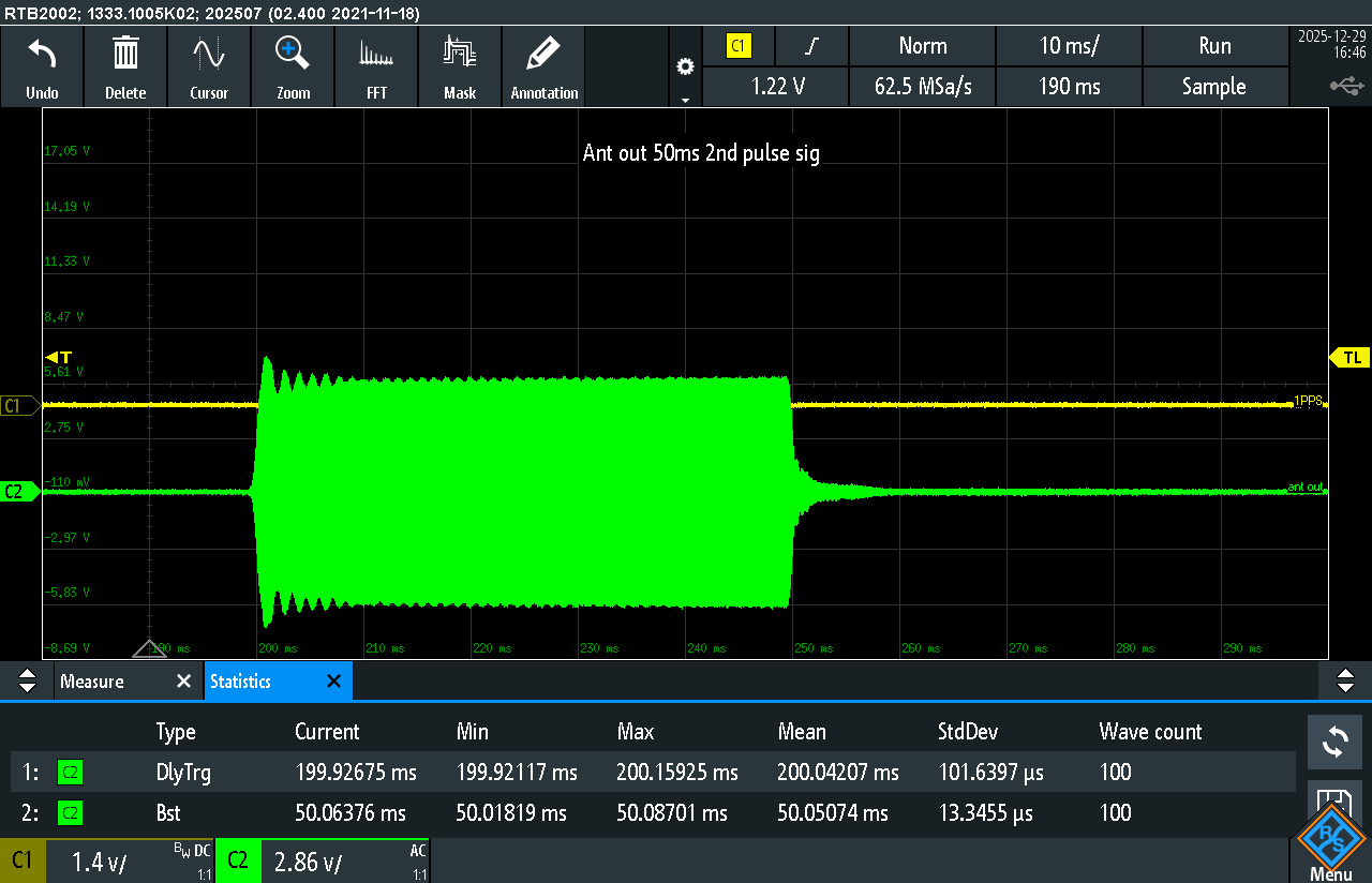
Pulse #2 (nominal 50 ms):
- Mean: 50.05074 ms
- Min–Max: 50.01819 … 50.08701 ms
- StdDev: 13.35 µs
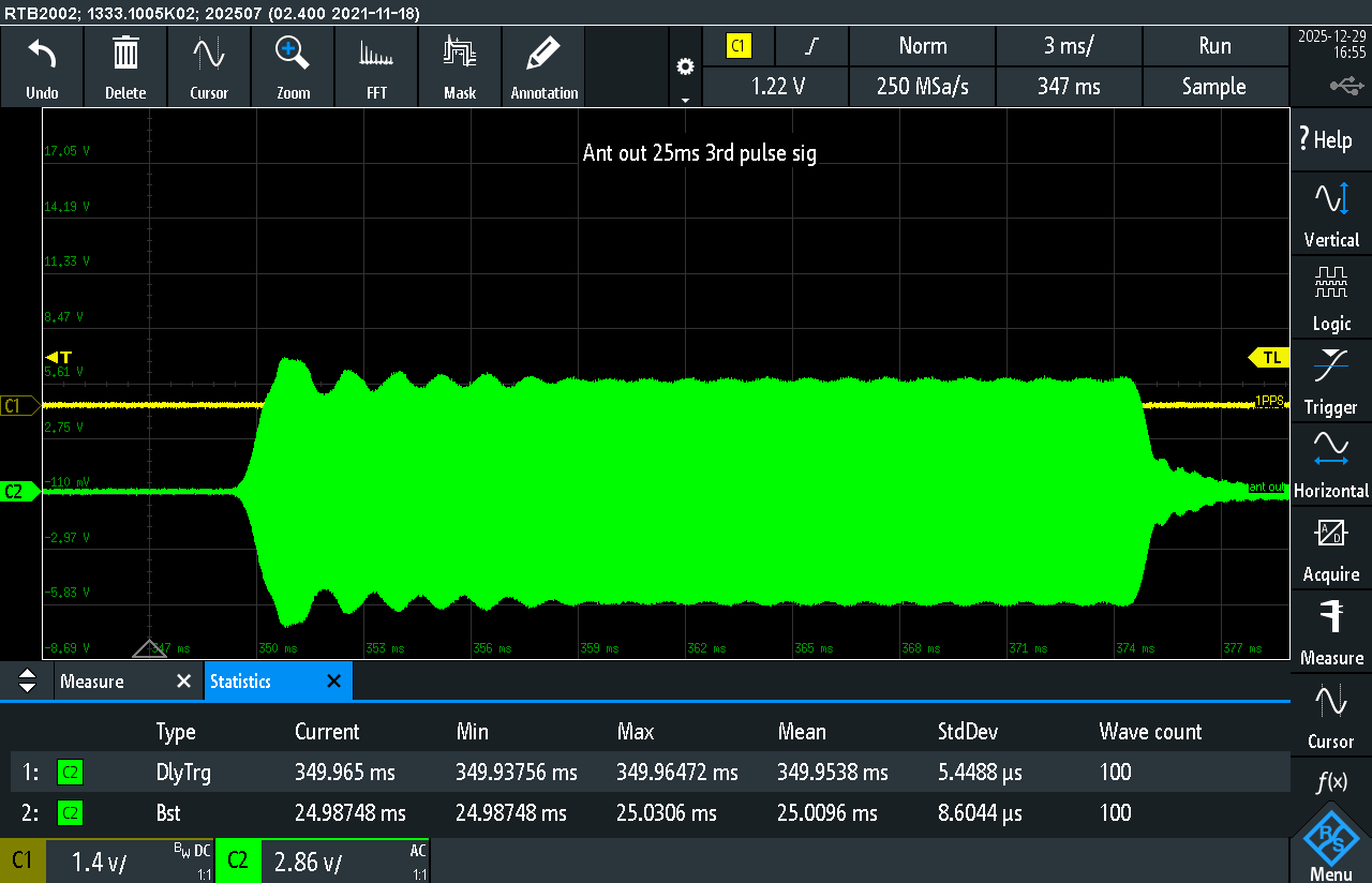
Pulse #3 (nominal 25 ms):
- Mean: 25.0096 ms
- Min–Max: 24.98748 … 25.0306 ms
- StdDev: 8.60 µs
Measured pulse positions relative to the trigger confirm the packet timing:
pulse #2 starts at about 200 ms, pulse #3 at about 350 ms.
4. 1PPS Reference and Time Alignment
The entire system is synchronized to a 1PPS reference signal, which is used:
as an absolute time marker
as a reference for the packet timing window
Recommended Method for Determining Pulse Timing
Pulse boundaries are defined using relative envelope levels at 10% / 50% / 90% of the envelope amplitude (from baseline to plateau).
- 50% level is used as the primary timing reference (pulse start and end)
- 10% and 90% levels are used to evaluate rise/fall behavior and signal chain effects such as filtering, group delay, bandwidth limits, and AGC
This approach improves measurement repeatability and reduces sensitivity to amplitude distortion, envelope shape, bandwidth limitations, and analog path artifacts
5. Generation Accuracy vs. Over-the-Air Measurement Limits
The accuracy of pulse generation and transmission in FMTLab intentionally exceeds the achievable accuracy of over-the-air measurements.
This means the contribution of the generator and transmit chain is negligible compared to errors introduced by the radio channel and the participant’s receive setup.
From antenna-output measurements, pulse duration variation is on the order of single-digit to tens of microseconds for pulse lengths of 25–100 ms.
Key points:
- packet timing is locked to the 1PPS reference
- pulse edges are generated deterministically and repeatably
- no long-term drift is observed during measurement sessions
As a result, the signal generation accuracy exceeds over-the-air measurement capabilities by at least 1–2 orders of magnitude in time.
This implies:
- the generator is not a limiting factor
- all observed deviations are caused by the transmission path, radio channel, and measurement method
- any setup capable of measuring pulse boundaries with better than ~0.1–0.2 ms accuracy fully meets FMTLab requirements and can compete on equal terms
6. Signal Levels and Methodology
Signal generation and measurement principles follow ITU-R Recommendation M.1177-4 as a general reference for time- and frequency-domain radio measurements.
FMTLab does not claim radar system compliance but uses these recommendations as a basis for reproducible measurements.
7. Principles of Working with FMTLab Signals
- No delays are compensated after the fact
- All distortions and edge behavior are considered part of the system
- The real signal chain is measured, not an idealized model
8. Pulse Generation Equipment
Pulse generation is performed using a Keysight EDU33211A laboratory signal generator operating in burst mode with external 1PPS synchronization.
Timing verification is performed using a Rohde & Schwarz RTB2002 digital oscilloscope.
Key requirements for the generator and signal chain:
- stable and repeatable time base
- external 1PPS synchronization capability
- deterministic burst timing
- absence of random jitter at the microsecond level
- repeatable rise and fall characteristics without random artifacts
The generator and operating mode ensure timing instability far below typical over-the-air measurement errors.
Therefore, signal generation inaccuracies do not affect FMTLab results and require no additional correction. The generator and transmit chain are treated as a reference source against which only the participant’s receive system and measurement method are evaluated.
Links to Official Equipment Specifications
- Keysight EDU33211A — pulse / function generator
Official device page with datasheet information, including burst operation modes and external synchronization support:
https://www.keysight.com/de/de/assets/3121-1004/data-sheets/EDU33210-Series-20-MHz-Function-Arbitrary-Waveform-Generators.pdf - Rohde & Schwarz RTB2002 — digital oscilloscope
Official page for the RTB2000 series, including bandwidth, sampling rate, and measurement capabilities:
https://scdn.rohde-schwarz.com/ur/pws/dl_downloads/dl_common_library/dl_brochures_and_datasheets/pdf_1/RTB2000_bro_en_3607-4270-12_v0700.pdf