FMT Test Transmission Format
This document defines the deterministic transmission format used for FMT test runs.
FMT Test Transmission Format
Band Slot Preamble (Tour Calibration)
Before each 15-minute FMT Test competition block, the transmitter sends a short preamble that helps participants estimate their current receive-side frequency offset right before the measurement interval.
- Short QST: ~30 s (CW)
- Calibration carrier: 60 s unmodulated carrier (CW) on the published calibration carrier frequency
Purpose: Measure this 60 s calibration carrier to estimate the current RX offset (Doppler + receiver chain). Apply the correction to your carrier frequency measurement for this tour. Using the calibration carrier is optional but recommended for best accuracy.
Note: The calibration carrier is not a separate contest task and does not replace the carrier blocks inside the 15-minute test. It is an additional reference sent immediately before the competition block.
Transmission Flow
Slot level (tour transmission): Short QST → Calibration carrier → FMT Test (15 min)
FMT Test competition block (15 min): Initial QST → Cycle start → Pulse → Carrier → Short QST → repeat (×6) → Sign-off
- Initial QST: 2 minutes
- Cycle (×6): Pulse 60 s → Carrier 60 s → Short QST ~12 s
- Final cycle ends with:
FMT TEST DE SN0FMT SK
Overview
- FMT Test competition block: fixed duration of 15 minutes
- Slot preamble: ~90 s (Short QST + Calibration carrier)
- Start aligned to a published UTC time
- Deterministic internal structure
- For pulse measurements, tune to the published USB pulse frequency (CW − 1 kHz). For carrier measurements, stay on the CW carrier frequency.
Signal Modes and Frequencies
FMT tour transmissions use two CW carrier frequencies (one for quick calibration, one for the actual test) and one additional USB signal for the pulse burst. This is intentional and designed to keep receiver operation simple and predictable.
Important: The values below are an example. Actual published frequencies may differ per tour, but the relationships (calibration vs competition carrier, and USB = CW − 1 kHz) remain the same. Calibration carrier frequency may differ from competition carrier frequency by design.
- Calibration carrier (CW, 60 s):
14 068 000.00 Hz
Unmodulated reference carrier sent immediately before the competition block to estimate current RX offset (Doppler + RX chain). - Competition CW carrier (CW):
14 068 050.22 Hz
CW identification and carrier measurement blocks inside the 15-minute FMT Test use this frequency. - Pulse burst (USB):
14 068 050.22 Hz - 1kHz = 14 067 050.22 Hzaudio tone 1 kHz
The pulse burst is transmitted in USB, modulated by a deterministic 1 kHz tone, as a three-pulse burst.
The pulse burst uses USB at exactly 1 kHz below the competition CW carrier frequency. This allows stations focused on carrier frequency measurements to stay tuned to the CW carrier frequency, while pulse measurements are done on the USB offset frequency.
Initial QST
Each transmission starts with a 2-minute CW identification phase used for tuning and confirming reception.
QST DE SN0FMT TEST FMT
Measurement Cycles
After the initial QST, six identical measurement cycles are transmitted. Each cycle lasts about 135 seconds and includes:
- Pulse signal (60 seconds)
- Unmodulated carrier (60 seconds)
- Short CW identification (about 12 seconds)
FMT TEST DE SN0FMT
Final Sign-off
In the final cycle, the CW identification serves as the sign-off:
FMT TEST DE SN0FMT SK
Timing and Calibration
All timing is derived from the published UTC start time and the fixed transmission structure. Receiver-side timing offsets are determined during separate calibration sessions and applied during result processing.
Frequency Usage
The carrier and pulse signals are transmitted on fixed, closely spaced frequencies. No frequency changes occur within a given signal type.
- Calibration carrier uses the published calibration carrier frequency (CW)
- CW identification and carrier measurements use the published competition CW carrier frequency
- Pulse measurements use the published USB frequency, which is exactly 1 kHz below the competition CW carrier frequency
This structure ensures repeatable measurements while keeping receiver operation simple and predictable.
What Is Measured
FMT measurements consist of three independent components. Each of them must be evaluated separately.
1. Pulse Burst (Pulse Duration)
The pulse signal is transmitted as a pulse burst. The first two pulses and the pauses between them are reference signals and are identical to those used during calibration sessions.
The measured value is the duration of the third pulse. The same measurement method should be used consistently for all cycles.
2. Offset Relative to 1PPS (Time Measurement)
The start of the first pulse in the burst has a fixed offset relative to the transmit-side 1PPS reference. This offset is one of the primary quantities to be measured.
We compare the received burst start to our local 1PPS, then apply receiver delay correction determined in calibration.
This station-specific delay is determined during calibration sessions, where the pulse burst starts exactly at the 1PPS boundary and has no intentional offset. The measured delay is stored as a constant and applied as a correction during contest data processing.
3. Carrier Frequency Measurement
Participants may use the 60 s calibration carrier transmitted immediately before the test block to estimate current RX offset and improve accuracy. The contest result is still based on the carrier blocks inside the 15-minute test.
During the carrier block, participants measure the carrier frequency independently from the pulse measurements.
The carrier is transmitted continuously for 60 seconds to allow averaging and high-resolution frequency estimation. The highest precision achievable by the receiving setup should be used.
Summary
- Pulse burst → duration of the third pulse
- First pulse start → offset relative to transmit-side 1PPS
- Carrier block → precise carrier frequency
Example of burst signal measurement and 1PPS offset
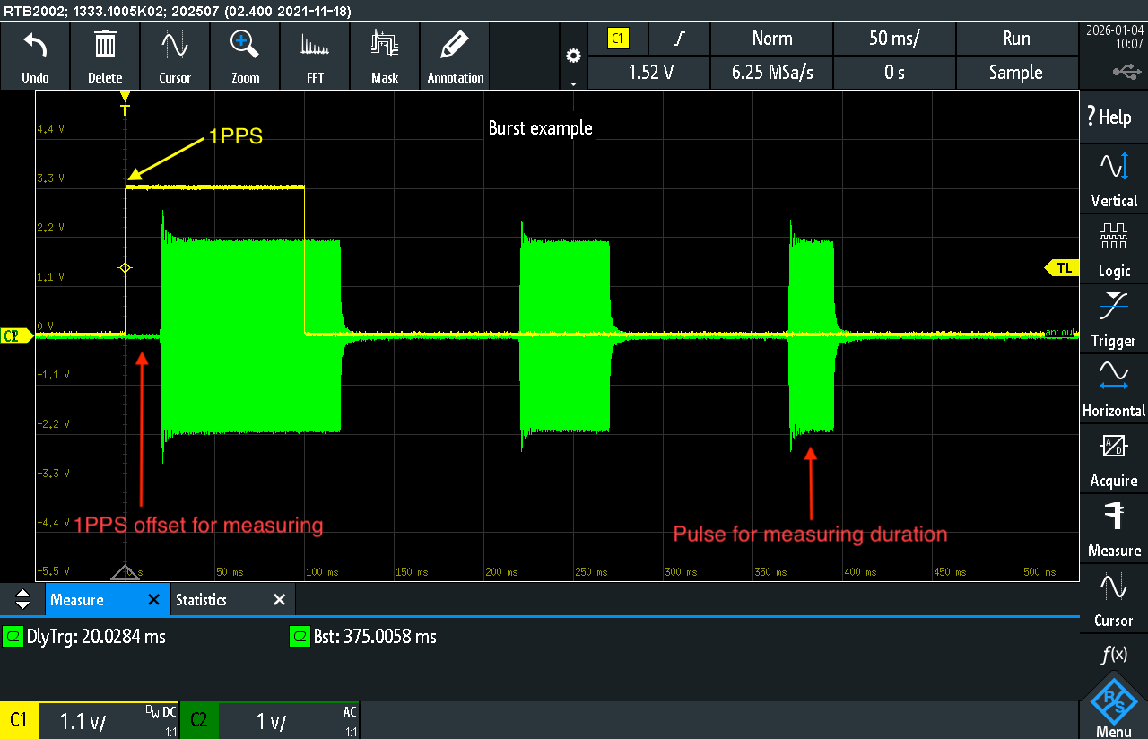
The image shows an example of a pulse burst measured by an FMT contest participant.
According to the FMT rules, one of the main tasks is to determine the burst start offset, specifically the offset of the first pulse relative to the 1PPS reference signal.
This type of measurement in FMT is referred to as 1PPS offset.
In the presented example, the first pulse starts 20 ms after the rising edge of the 1PPS signal.
Components of the measured offset
The measured offset is not the final result.
It always includes several components:
- the local delay of the participant’s receiving chain (antenna, receiver, filtering, digital processing, measurement equipment);
- the signal propagation delay from the transmitter to the receiver;
- any actual offset introduced at the transmitter side.
In this example:
- the receiver chain delay is 4 ms;
- the signal propagation delay is 8 ms.
The total system delay is therefore:
4 ms + 8 ms = 12 ms
Calculation of the correct 1PPS offset value
To obtain the correct result, the total system delay must be subtracted from the measured offset:
20 ms − 12 ms = 8 ms
This value (8 ms) is the correct 1PPS offset and must be entered by the participant in the result submission form on the FMT portal.
Requirement for receiver calibration
Correct measurement of 1PPS offset is not possible without prior calibration of the participant’s receiving system.
Calibration is performed during dedicated sessions where:
- the transmitter generates the pulse burst without any intentional offset, fully synchronized to 1PPS;
- the start of the first pulse at the transmitter coincides with the 1PPS edge.
Under these conditions, the offset measured by the participant represents only the delay of their own receiving chain.
This value is recorded and later used as a fixed correction when measuring 1PPS offset.
Importance of the pulse burst structure
The standardized pulse burst used in FMT is a critical element of the measurement process.
The burst structure:
- provides an unambiguous reference for burst start detection;
- enables reliable alignment of the first pulse to the 1PPS reference;
- contains internal timing elements with fixed parameters;
- allows verification of measurement stability and repeatability.
Pulse duration measurement
The image also highlights the third pulse in the burst, whose duration must be measured as part of the contest.
The timing of the first two pulses and all pauses between pulses are fixed constants, defined by the signal specification, and must not be measured or adjusted by participants.
Only the duration of the third pulse is subject to measurement, using the recommended signal edge processing methodology.